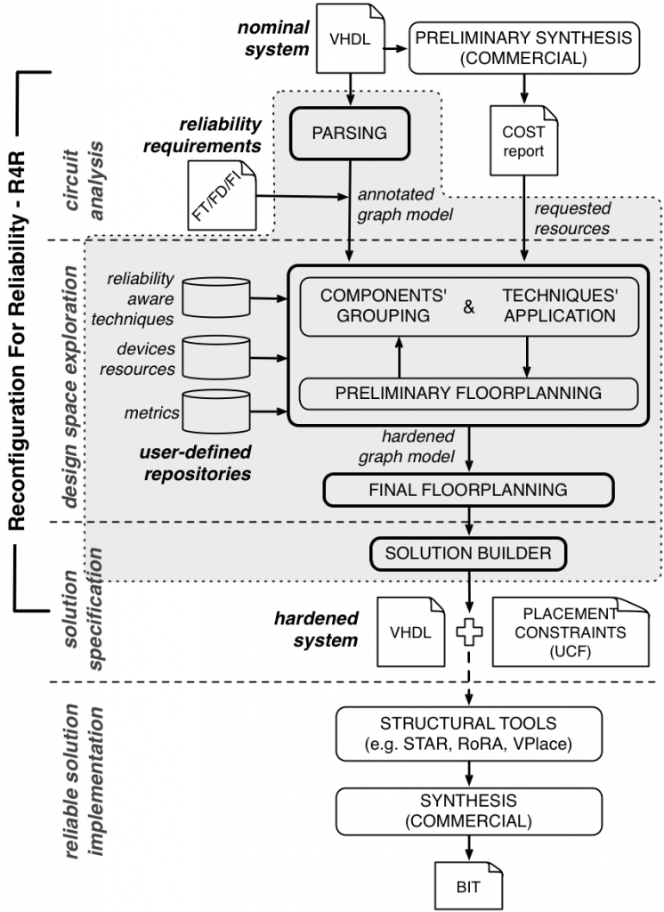
The designed and developed framework for achieving fault mitigation properties via reconfiguration is the following one.

It consists of three main tasks:
- Circuit analysis, to collect the information needed for the design space exploration;
- Design space exploration, core of the design flow;
- Solution specification, to synthesize the chosen reliability-aware design solution.
The circuit analysis task takes as input the VHDL description of circuit under consideration, to be parsed and synthesized; possibly, other hardware description languages, such as Verilog, could be supported as well. Parsing is used to build an agile representation of the circuit based on graphs, and The circuit analysis task takes as input the VHDL description of circuit under consideration, to be parsed and synthesized; possibly, other hardware description languages, such as Verilog, could be the preliminary synthesis is performed for determining the implementation costs and the characteristics of each part of the circuit description. Synthesis is carried out by using commercial tools, such as the Xilinx’s tool-chain, and the obtained information in terms of the necessary resources are used to estimate the cost of the hardened solution, which fundamentally exploits hardware redundancy strategies. In this phase the fault management requirements expressed by the designer for the various parts of the circuit are analyzed and the internal graph-based representation is decorated with this information, used to drive the hardening process.
The design space exploration is the core of the proposed design flow; it takes as input the graph-based representation of the circuit annotated with its costs and requirements, as well as data from several repositories containing the necessary information on the set of reliability-oriented techniques provided for hardening the circuit, the model of the FPGA devices describing the available resources, and the set of metrics provided for the evaluation of the generated solutions.
This task can be seen as composed by two phases: i) a components’ grouping and techniques’ application phase and ii) a preliminary floorplanning one.
The former performs a fast, automated design space exploration for identifying the most promising hardened system, i.e., the one representing an optimal trade-off between costs and benefits derived from the application of the techniques. It is devoted to the analysis of the various possible applications of the available reliability-oriented design techniques in different ways, on the several parts of the circuit.
The latter analyzes, for each identified solution, the suitable placements on the reconfigurable fabric to guarantee that all necessary resources (number and type) are available, given their heterogeneous distribution within the device, and providing an accurate estimation of the costs of the circuit. The design space exploration task altogether identifies Pareto-optimal solutions with respect to several figures of merit, taking into account occupied area, reconfiguration time and fulfilling the fault management requirements which are considered as a constraint. For this set of candidate solutions a final floorplanning is performed to further optimize the placement of the hardened implementations, thus deriving the constraints to be used during synthesis.
The solution specification task takes in input the structure and the characteristics of the best solutions identified in the previous step, among which the designer can select the one to be implemented, and produces the VHDL description of the final solution and the other files containing the reliability-driven placement constraints. Such data is generated in a semi-automated way and can be synthesized by means of commercial tools. At this point, in order to guarantee that the the considered faults cause a single module failure, tools such as STAR + VPlace + RoRA ([SV+2007,STE2009,SV2006]) can be used to obtain a suitable place and route which maintains the reliability-driven constraints.
In particular, the solution builder starts from the hardened graph model with all the additional information and re-builds the VHDL description of the modified circuit that includes redundant copies of the original components where needed, as well as the additional components, such as voters and comparators made available by the specific repository, and the related placement constraints’ file.